
RBSE Class 12th 2019 Physics-SS-40-1-2019-With Solution Previous Year Papers
Physics-SS-40-1-2019-With Solution from the 2019 exam year is part of the Class 12th previous year papers archive on RBSE Solution. Many learners start here after finishing the textbook to see how questions were actually framed on the Rajasthan Board of Secondary Education (RBSE) paper.
Treat this question paper as a mock under gentle timing first, then as a marking exercise the second time. The introduction on this page is written only for this subject-and-year pair, not copied from other pages.
Bookmark the link if you coach juniors — the layout stays stable for search engines and classroom sharing.
Paper details
Quick reference for this previous year papers page — confirm board, class, and year & subject before you study.
| Board | RBSE |
|---|---|
| Class | Class 12th |
| Exam year | 2019 |
| Subject | Physics-SS-40-1-2019-With Solution |
| Resource type | Previous Year Papers |
| Category | RBSE Previous Year Question Papers |
| Website | RBSE Solution |
The table summarises this Previous Year Papers resource. Confirm RBSE, Class 12th, year 2019, and subject Physics-SS-40-1-2019-With Solution before studying.
RBSE Solution organises previous year papers so each URL carries chapter-specific guidance — better for students and for search engines than one generic paragraph for the whole class.
Turning 2019 papers into insight
One Physics-SS-40-1-2019-With Solution paper reveals style; several from the same year reveal pattern. After this page, open sibling subjects listed below to see whether marks cluster in certain units.
Keep rough work dated in your notebook. Examiners in Class 12th expect clear numbering even in practice sessions.
RBSE Class 12th 2019 Physics-SS-40-1-2019-With Solution
Scroll through the Previous Year Papers pages for Physics-SS-40-1-2019-With Solution (2019).
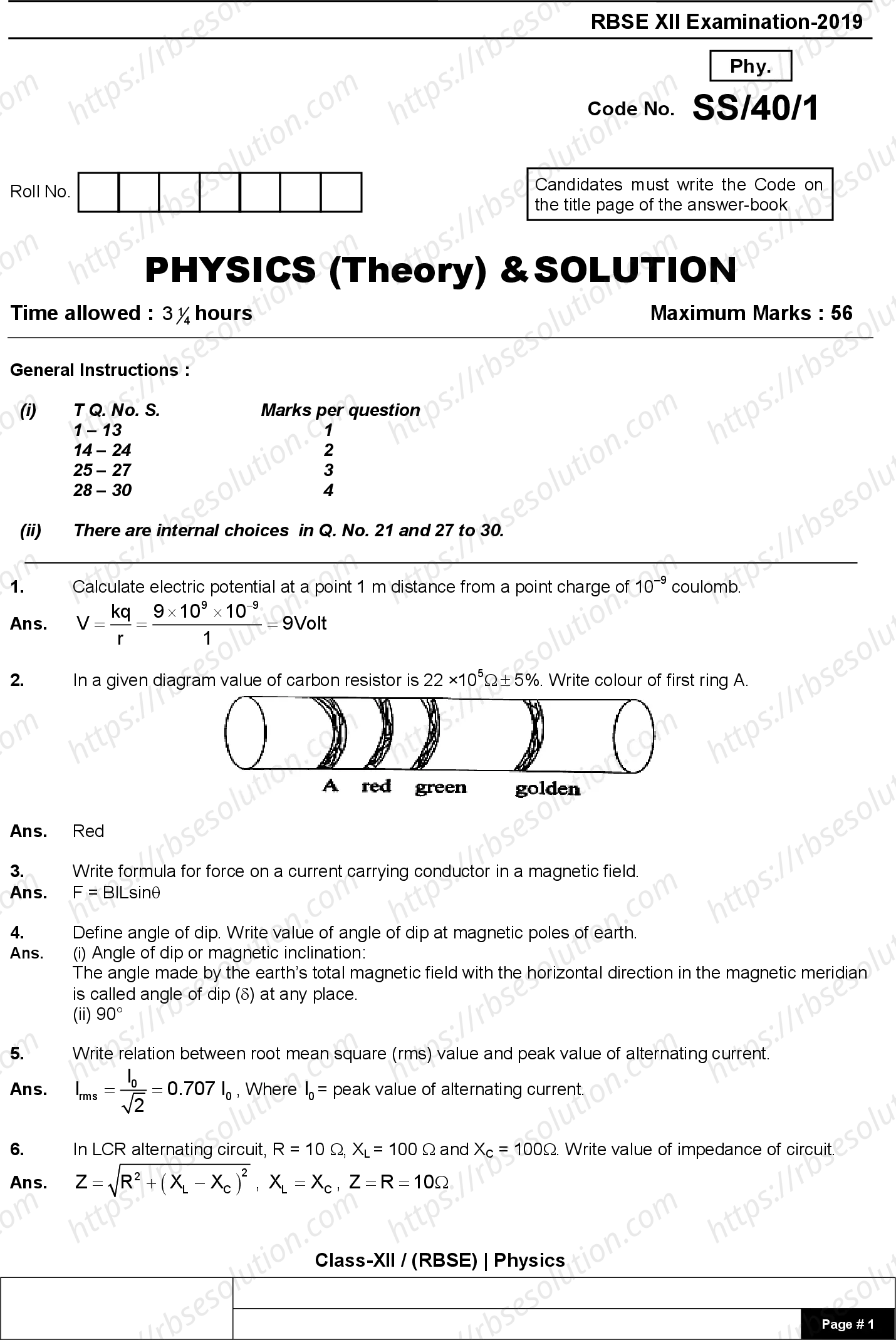


Rajasthan Board Class 12th Physics-SS-40-1-2019-With Solution 2019 solved Previous Year Question Papers
RBSE XII Examination – 2019
Physics (Theory) & Solution
Code No. SS/40
Time allowed: 3¼ hours Maximum Marks: 56
General Instructions:
- Q. No. 1–4: 1 mark each
- Q. No. 5–24: 2 marks each
- Q. No. 25–27: 3 marks each
- Q. No. 28–30: 4 marks each
- There are internal choices in Q. No. 27 and 27 to 30.
Question 1
Calculate electric potential at 0.07 m distance from a point charge of 4 × 10⁻⁷ coulomb.
Solution:
V = kq / r = (9 × 10⁹ × 4 × 10⁻⁷) / 0.07 = 9 Volt
Question 2
In a given diagram, the value of a carbon resistor is 22 × 10⁰ Ω ± 5%. Write the colour of the first ring A.
(Diagram reference: rings – green, golden)
Answer: Red
Question 3
Write the formula for force on a current-carrying conductor in a magnetic field.
Answer: F = B I L sin θ
Question 4
Define angle of dip. Write the value of angle of dip at the magnetic poles of the earth.
Answer:
(i) Angle of dip (magnetic inclination): The angle made by the earth's total magnetic field with the horizontal direction in the magnetic meridian is called the angle of dip (δ) at any place.
(ii) At magnetic poles, the angle of dip is 90°.
Question 5
Write the relation between root mean square (rms) value and peak value of alternating current.
Answer:
Irms = I₀ / √2 = 0.707 I₀, where I₀ is the peak value of alternating current.
Question 6
In an LCR alternating circuit, R = 700 Ω, XL = 700 Ω and XC = 700 Ω. Write the value of impedance of the circuit.
Answer:
Z = √[R² + (XL – XC)²] = √[700² + (700 – 700)²] = √(700²) = 700 Ω
Page 1 of 18
Physics (RBSE XII Examination 2019)
Question 40
Write relation between power of lens and its focal length.
Answer:
Power of lens = 1⁄Focal length (in m)
Question 41
Define threshold frequency.
Answer:
For a given photosensitive material, there exists a certain minimum cut-off frequency below which no photoelectrons are emitted, howsoever high the intensity of incident radiation. This frequency is called threshold frequency.
Question 42
Draw diagram of the experimental arrangement of Davisson and Germer experiment.
Answer:
Here the electrons emitted by the hot filament of an electron gun are accelerated by applying a suitable potential difference V between the cathode and anode.
                    L.T.B.
                       |
    Filament ──► [Electron Gun] ──► Incident electron beam ──► Ni Crystal
                       |                                          |
                    H.T.B.                                     Diffracted
                       |                                      electron beam
                    Anode                                         |
                                                              [Movable Collector]
                                                                     |
                                                              To galvanometer
                                                         (Vacuum chamber)
Experimental arrangement of Davisson and Germer experiment
Question 43
Write name of series of hydrogen spectrum for transitions from n = 2,3,4,5... to ground energy level.
Answer:
Lyman Series
Question 44
Write value of output Y in diagram.
Answer:
Y = A + B (OR gate output)
Question 45
Define modulation.
Answer:
The original low frequency message signal cannot be transmitted to long distances. Hence, modulation of the low frequency signal is done. Modulation is the phenomenon of superimposing the low frequency message signal (called the modulating signal) on a high frequency wave (called the carrier wave).
Question 46
In electromagnetic waves, write the value of (A) angle and (B) phase difference, between electric field E and magnetic field B.
Answer:
(A) Angle = 90°
(B) Phase difference = Zero
Question 47
Define:
(a) Electric dipole moment
(b) Equipotential surface
Answer:
(a) Electric Dipole moment: It measures the strength of an electric dipole. The dipole moment of an electric dipole is a vector whose magnitude is the product of magnitude of both charges and the separation between the two opposite charges, and the direction is along the dipole axis from the negative to the positive charge.
p = q(2a)
-q ──── 2a ──── +q
(b) Equipotential surface: Any surface that has same electric potential at every point on it is called an equipotential surface.
45. Calculate the value of unknown resistance R in given circuit. If Wheatstone bridge is in balanced condition.
Solution:
For a balanced Wheatstone bridge, the condition is:
\(\frac{P}{Q} = \frac{R}{S}\)
Given: P = 4 Ω, Q = 5 Ω, S = 6 Ω
\(\frac{4}{5} = \frac{R}{6}\)
\(R = \frac{4 \times 6}{5} = \frac{24}{5} = 4.8 \, \Omega\)
Correct Answer: R = 4.8 Ω
6. (a) Define Curie temperature.
Answer: The temperature at which a ferromagnetic substance loses its ferromagnetic properties and becomes paramagnetic is called Curie temperature or Curie point (Tc).
6. (b) The pole strength of poles of a bar magnet of effective length 0.4 m is 40 A-m. Calculate its magnetic moment.
Solution:
Given: Effective length (2l) = 0.4 m, Pole strength (m) = 40 A-m
Magnetic moment (M) = m × (2l)
M = 40 × 0.4 = 16 A-m²
Correct Answer: M = 16 A-m²
7. Write Lenz's law. Lenz's law obeys law of conservation of energy. Explain.
Answer:
Lenz's law: The direction of induced current in a circuit is such that it opposes the cause or the change which produces it.
Explanation of conservation of energy:
When a magnet is moved towards or away from a closed coil, the induced current always opposes the motion of the magnet. For example, when the north pole of a magnet is brought closer to a coil, the face of the coil towards the magnet develops north polarity and repels the north pole of the magnet. Work must be done to move the magnet closer against this repulsive force. Similarly, when the north pole is moved away, the coil's face develops south polarity and attracts the north pole, requiring work to move it away. This work done against the magnetic force is converted into electrical energy in the form of induced current.
If Lenz's law were not valid, the induced current would flow in the opposite direction, causing the magnet to accelerate without any work input. This would create a perpetual motion machine, violating the law of conservation of energy. Thus, Lenz's law is a direct consequence of the conservation of energy.
प्रश्न 48
प्रश्न: निम्नलिखित की परिभाषाएँ लिखिए:
(a) पूर्ण आंतरिक परावर्तन (Total internal reflection)
(b) प्रकाश का विवर्तन (Diffraction of light)
उत्तर:
(a) पूर्ण आंतरिक परावर्तन (Total Internal Reflection):
जब प्रकाश किसी सघन माध्यम से विरल माध्यम में जाता है, तो अंतरापृष्ठ पर प्रकाश का कुछ भाग सघन माध्यम में वापस परावर्तित हो जाता है और कुछ भाग विरल माध्यम में अपवर्तित हो जाता है। इस परावर्तन को आंतरिक परावर्तन कहते हैं। कुछ विशेष परिस्थितियों में, संपूर्ण आपतित प्रकाश सघन माध्यम में वापस परावर्तित हो जाता है। इस घटना को पूर्ण आंतरिक परावर्तन कहते हैं।
[पूर्ण आंतरिक परावर्तन का चित्र - जल-वायु अंतरापृष्ठ]
(b) प्रकाश का विवर्तन (Diffraction of Light):
प्रकाश का नुकीले कोनों के चारों ओर मुड़ने और अपारदर्शी बाधाओं की ज्यामितीय छाया के भीतर प्रकाश के फैलने की घटना को प्रकाश का विवर्तन कहते हैं। इस प्रकार प्रकाश अपने सरल रेखीय पथ से विचलित हो जाता है। जब छिद्र या बाधा के आयाम प्रकाश की तरंगदैर्ध्य के तुलनीय होते हैं, तो यह विचलन अधिक स्पष्ट हो जाता है।
[प्रकाश के विवर्तन का चित्र]
प्रश्न 49
प्रश्न:
(a) मैलस नियम (Malus law) से संबंधित सूत्र लिखिए।
(b) जब प्रकाश किसी पारदर्शी शीट पर 60° के कोण पर आपतित होता है, तो परावर्तित प्रकाश पूर्णतः समतल ध्रुवित हो जाता है। पदार्थ का अपवर्तनांक और अपवर्तन कोण ज्ञात कीजिए।
उत्तर:
(a) मैलस नियम (Malus Law):
इस नियम के अनुसार, "जब पूर्णतः समतल ध्रुवित प्रकाश की एक किरण किसी विश्लेषक पर आपतित होती है, तो विश्लेषक से संचरित प्रकाश की परिणामी तीव्रता I, विश्लेषक और ध्रुवक के संचरण तलों के बीच के कोण (θ) की कोज्या के वर्ग के अनुक्रमानुपाती होती है।"
I = I₀ cos²θ
जहाँ I₀, ध्रुवक P से गुजरने के बाद ध्रुवित प्रकाश की तीव्रता है। [इस नियम को कोज्या वर्ग नियम भी कहते हैं।]
(b) अपवर्तनांक और अपवर्तन कोण की गणना:
ब्रूस्टर के नियम के अनुसार, जब परावर्तित प्रकाश पूर्णतः ध्रुवित होता है, तब:
μ = tan ip
जहाँ ip ध्रुवण कोण (आपतन कोण) है।
दिया गया है: ip = 60°
μ = tan 60° = √3 ≈ 1.73
अतः पदार्थ का अपवर्तनांक (μ) = √3 ≈ 1.73
ब्रूस्टर के नियम से, ध्रुवण कोण और अपवर्तन कोण के बीच संबंध:
ip + r = 90°
r = 90° - ip = 90° - 60° = 30°
अतः अपवर्तन कोण (r) = 30°
20. Calculate de Broglie wavelength of a wave associated with an electron, which is accelerated through a potential difference of 100 V.
Solution:
For an electron accelerated through a potential difference V, the de Broglie wavelength λ is given by:
λ = h / √(2meV)
Where h = 6.63 × 10⁻³⁴ Js, m = 9.1 × 10⁻³¹ kg, e = 1.6 × 10⁻¹⁹ C, V = 100 V
λ = 6.63 × 10⁻³⁴ / √(2 × 9.1 × 10⁻³¹ × 1.6 × 10⁻¹⁹ × 100)
λ = 6.63 × 10⁻³⁴ / √(2.912 × 10⁻⁴⁷)
λ = 6.63 × 10⁻³⁴ / (5.396 × 10⁻²⁴)
λ = 1.228 × 10⁻¹⁰ m = 1.228 Å
Correct Answer: λ = 1.228 Å
24. Derive formula for obtaining internal resistance of a primary cell with help of potentiometer. Draw circuit diagram.
Derivation:
Circuit Diagram:
[Circuit diagram: Battery connected across potentiometer wire AB. Cell ε with key K₁ and jockey. Resistance box R and key K₂ in series with cell.]
Procedure:
- Close key K₁ so that constant current flows through potentiometer wire AB.
- With key K₂ open, move jockey along AB to find balance point for emf ε of the cell. Let balancing length be l₁. If k is potential gradient, then ε = k l₁.
- Now introduce resistance R from resistance box and close key K₂. Find balance point for terminal potential difference V of the cell. Let balancing length be l₂. Then V = k l₂.
Dividing the two equations:
ε / V = l₁ / l₂
Let r be internal resistance of the cell. When cell is shunted with resistance R, current I flows. From Ohm's law:
ε = I(R + r) and V = IR
Therefore, ε / V = (R + r) / R
Equating with above: l₁ / l₂ = (R + r) / R
Solving for r:
r = R (l₁ / l₂ - 1) = R (l₁ - l₂) / l₂
Formula: Internal resistance, r = R (l₁ - l₂) / l₂
OR
Explain the method to find unknown resistance with the help of Meter Bridge. Draw circuit diagram.
Meter Bridge (Slide Wire Bridge):
It is the simplest practical application of Wheatstone bridge used to measure an unknown resistance.
Principle: Its working is based on the principle of Wheatstone bridge. When the bridge is balanced:
P / Q = R / S
Circuit Diagram:
[Circuit diagram: A meter bridge wire AB of length 1 m. Unknown resistance X in left gap, known resistance R in right gap. Galvanometer connected between middle point and jockey. Battery connected across ends.]
Method:
- Connect unknown resistance X in left gap and known resistance R in right gap of the meter bridge.
- Connect a battery across ends A and B of the wire.
- Slide the jockey along the wire to find point where galvanometer shows zero deflection (balance point).
- Let balancing length from end A be l cm. Then length from end B is (100 - l) cm.
- At balance, X / R = l / (100 - l)
- Therefore, unknown resistance X = R × l / (100 - l)
Formula: X = R × l / (100 - l)
Measurement of Unknown Resistance by a Metre Bridge
Construction:
- It consists of usually one metre long manganin wire of uniform cross-section, stretched along a metre scale fixed over a wooden board and with its two ends soldered to two L-shaped thick copper strips A and C.
- Between these two copper strips, another copper strip B is fixed so as to provide two gaps ab and a₁b₁.
- A resistance box R.B. is connected in the gap ab and the unknown resistance S is connected in the gap a₁b₁.
- A source of emf ε is connected across AC. A movable jockey and a galvanometer are connected across BD, as shown in Figure.
Figure: Measurement of unknown resistance by a metre bridge
[Diagram: A wire AC of length 100 cm with a jockey at B. A resistance box R in gap ab, unknown resistance S in gap a₁b₁. Galvanometer G connected between B and D. Battery ε connected across A and C.]
Working:
After selecting a suitable resistance R from the resistance box, the jockey is moved along the wire AC till there is no deflection in the galvanometer. This is the balanced condition of the Wheatstone bridge. If P and Q are resistances of the parts AB and BC of the wire, then for the balanced condition of the bridge, we have:
P / Q = R / S
Let total length of wire AC = 100 cm and AB = l cm, then BC = (100 − l) cm. Since the bridge wire is of uniform cross-section, therefore,
Resistance of wire ∝ length of wire or R ∝ l
P / Q = (resistance of AB) / (resistance of BC) = (σ × l) / (σ × (100 − l)) = l / (100 − l)
where σ is the resistance per unit length of the wire.
Hence:
R / S = l / (100 − l)
or S = R × (100 − l) / l
Knowing l and R, the unknown resistance S can be determined.
22. Write Niels Bohr’s any two postulates for hydrogen atom (hydrogen like ions).
Bohr's Postulates:
(i) First Postulate (Stationary Orbits): An electron in an atom revolves in certain stable orbits without emitting radiant energy, contrary to classical electromagnetic theory. These are called stationary states, each having a definite total energy.
(ii) Second Postulate (Quantization of Angular Momentum): The electron revolves around the nucleus only in those orbits for which the angular momentum is an integral multiple of h/2π, where h is Planck's constant (6.63 × 10⁻³⁴ J·s).
Thus, angular momentum L = mvr = nh/2π, where n = 1, 2, 3... (principal quantum number).
(iii) Third Postulate (Energy Transitions): An electron can jump from a higher energy orbit to a lower energy orbit, emitting a photon of energy equal to the energy difference between the two states. The frequency of the emitted photon is given by hν = Ei – Ef, where Ei and Ef are the initial and final energies.
23. (a) Select acceptor type impurity among the following: Arsenic (As), Antimony (Sb), Gallium (Ga) and Phosphorous (P). (b) Draw symbol of Zener diode.
(a) Acceptor impurity: Gallium (Ga) (it is a trivalent element).
(b) Symbol of Zener diode:
Anode ──►|── Cathode
       (Zener diode)
24. The magnitude of electric field E at a point in free space is 300 V/m. Find the magnitude of magnetic field B at this point. Velocity of light is 3 × 10⁸ m/s.
Solution:
In free space, the relation between electric field (E) and magnetic field (B) for an electromagnetic wave is: c = E / B, where c is the speed of light.
Given: E = 300 V/m, c = 3 × 10⁸ m/s.
Therefore, B = E / c = 300 / (3 × 10⁸) = 1 × 10⁻⁶ T.
Answer: B = 1 × 10⁻⁶ T (or 1 μT).
25. Write Rutherford – Soddy law of radioactive decay and derive related equation. Draw exponential decay curve of a radioactive substance. Write ratio of half life and mean life of a radioactive substance.
(a) Rutherford-Soddy Law (Radioactive Displacement Laws):
- When a radioactive nucleus emits an α-particle, its atomic number decreases by 2 and mass number decreases by 4.
- When a radioactive nucleus emits a β-particle, its atomic number increases by 1 but mass number remains the same.
- Emission of a γ-particle does not change the mass number or atomic number.
(b) Derivation of Decay Equation:
The law states that the rate of decay is proportional to the number of undecayed nuclei present at that time.
Let N be the number of undecayed nuclei at time t. Then, dN/dt = –λN, where λ is the decay constant.
Rearranging: dN/N = –λ dt.
Integrating both sides: ∫ dN/N = –λ ∫ dt ⇒ ln N = –λt + C.
At t = 0, N = N0 (initial number), so C = ln N0.
Thus, ln (N/N0) = –λt ⇒ N = N0 e–λt.
This is the exponential decay equation.
(c) Exponential Decay Curve:
N
|
|    *
|   * *
|  *   *
| *     *
|*       *
|__________ t
(d) Ratio of Half-life and Mean Life:
Half-life (T1/2) = ln 2 / λ = 0.693 / λ.
Mean life (τ) = 1 / λ.
Therefore, ratio T1/2 : τ = 0.693 : 1, or T1/2 = 0.693 τ.
Radioactive Decay Law
The number of nuclei disintegrating per second of a radioactive sample at any instant is directly proportional to the number of undecayed nuclei present in the sample at that instant.
Let
- N₀ = the number of radioactive nuclei present initially at time t = 0 in a sample of radioactive substance.
- N = the number of radioactive nuclei present in the sample at any instant t, and
- dN = the number of radioactive nuclei which disintegrate in the small time interval dt.
According to radioactive law, the rate of decay at any instant is proportional to the number of undecayed nuclei, i.e.,
Mathematical form of radioactive decay law:
dN/dt = -λN
where λ is a proportionality constant called the decay or disintegration constant. Here the negative sign shows that the number of undecayed nuclei (N) decreases with time.
The above equation can be written as:
dN/N = -λ dt
Integrating, ∫ dN/N = -λ ∫ dt
or loge N = -λt + C
where C is a constant of integration.
At t = 0, N = N₀, therefore from equation (2), we get loge N₀ = C
Then the equation (2) becomes:
loge N = -λt + loge N₀
or loge (N/N₀) = -λt
or N/N₀ = e-λt
or N = N₀ e-λt (Another mathematical form of radioactive decay law)
(b) Graph showing variation of number of undecayed nuclei with time:
Decay curve for a radioactive element
Number of undecayed nuclei at time t
N₀ → N₀/2 → N₀/4 → N₀/8 → ...
Time (t): 0 → T1/2 → 2T1/2 → 3T1/2 → 4T1/2 → ...
(c) Relation between half life and mean life:
We know that:
τ = 1/λ (where τ is mean life) ...(1)
T1/2 = 0.693/λ ...(2)
From (1): λ = 1/τ
Put in (2): T1/2 = 0.693 / (1/τ)
T1/2 = 0.693 τ
or τ = T1/2 / 0.693
Class-XII / (RBSE) | Physics
26. Describe the experimental set up for obtaining output characteristic curve of a PNP transistor in common emitter configuration with suitable circuit diagram. Also draw the curve obtained.
Common Emitter Characteristics
The common emitter characteristics are graphs drawn between appropriate voltages and currents for a transistor when its emitter is taken as the common terminal and grounded (zero potential), the base is the input terminal, and the collector is the output terminal.
Experimental Setup
The emitter-base junction is forward biased by means of battery VEE through rheostat Rh1. The emitter-collector circuit is reverse biased by means of battery VCC through rheostat Rh2. The base-emitter voltage (VBE) and the collector-emitter voltage (VCE) are measured by high resistance voltmeters. The base current (IB) is measured by a microammeter and the collector current (IC) by a milliammeter.
Input Characteristic
A graph showing the variation of base current IB with base-emitter voltage VBE at constant collector-emitter voltage VCE is called the input characteristic of the transistor. Two such curves for two different collector-emitter voltages have been plotted in the figure.
Input Characteristic Curve:
VCE = 4 volts (upper curve), VCE = 0 volts (lower curve)
X-axis: Base to emitter voltage (VBE) in volts — 0, 0.2, 0.4, 0.6, 0.8, 1.0, 2, 4, 6
Y-axis: Base current (IB) in μA
(Curve shows IB increasing slowly at first, then rising steeply after about 0.6 V)
Output Characteristic
A graph showing the variation of collector current IC with collector-emitter voltage VCE at constant base current IB is called the output characteristic of the transistor. The figure shows such curves for different values of IB.
Output Characteristic Curve:
X-axis: Collector to emitter voltage (VCE) in volts — 0, 0.5, 1, 1.5, 2, 2.5, 3, 3.5, 4
Y-axis: Collector current (IC) in mA
Curves for different base currents (IB):
- IB = 0 μA (lowest curve, near zero)
- IB = 10 μA
- IB = 20 μA
- IB = 30 μA
- IB = 40 μA
- IB = 50 μA (highest curve)
(Each curve rises steeply initially, then becomes nearly flat after about 1-2 V, showing saturation region)
Select possible value of common base current amplification factor α of a transistor among the following: 0.9, 9, 9, 49 and 99.
Answer: The possible value of common base current amplification factor α of a transistor is 0.9.
Explanation: The common base current gain (α) is defined as the ratio of collector current to emitter current (α = IC/IE). For a transistor, α is always less than 1 (typically between 0.9 and 0.99). Among the given options, only 0.9 satisfies this condition. Values like 9, 49, and 99 are greater than 1 and are not possible for α.
27. Draw vector diagram (phasor diagram) for a series RLC circuit which is connected with an alternating voltage source and determine the expression for impedance of the circuit.
Series LCR Circuit
Suppose a resistance R, an inductance L, and a capacitance C are connected in series to a source of alternating emf given by:
E = E₀ sin ωt
Phasor Diagram
- Voltage across R (VR): VR = I R is in phase with current I. So phasors VR and I are in the same direction. Amplitude: VR = I₀ R.
- Voltage across L (VL): VL = I XL leads the current I by π/2 rad. So phasor VL lies π/2 rad anticlockwise with respect to phasor I. Amplitude: VL = I₀ XL.
- Voltage across C (VC): VC = I XC lags behind the current I by π/2 rad. So phasor VC lies π/2 rad clockwise with respect to phasor I. Amplitude: VC = I₀ XC.
Phasor diagram for a series LCR circuit (when XL > XC):
As VL and VC are in opposite directions, their resultant is (VL – VC). By parallelogram law, the resultant of VR and (VL – VC) must be equal to the applied emf E₀, given by the diagonal of the parallelogram.
E₀² = (VR)² + (VL – VC)² = (I₀ R)² + (I₀ XL – I₀ XC)² = I₀² [R² + (XL – XC)²]
∴ I₀ = E₀ / √[R² + (XL – XC)²]
Impedance of the Circuit
Clearly, √[R² + (XL – XC)²] is the effective resistance of the series LCR circuit which opposes or impedes the flow of current through it and is called its impedance. It is denoted by Z and its SI unit is ohm (Ω).
Z = √[R² + (XL – XC)²]
Impedance triangle (when XL > XC):
The relationship between R, (XL – XC), and Z can be represented by a right-angled triangle where:
- Base = R
- Perpendicular = (XL – XC)
- Hypotenuse = Z
RBSE XII Examination - 2019
OR
Derive an expression for induced emf in a rod rotating in a uniform magnetic field. Draw necessary diagram.
Solution:
Consider a rod of length L rotating in a uniform magnetic field B perpendicular to the plane of rotation. The rod rotates about one end O with angular velocity ω.
Point O will be at a higher potential than point A.
Suppose the rod completes one revolution in time T.
Area swept in one rotation = πL²
Change in flux in one rotation = B × πL²
Induced emf = Rate of change of magnetic flux
= Change in flux / Time
= BπL² / T
= BπL² / (2π/ω)
= (BωL²) / 2
Therefore, |e| = (1/2) BωL²
28. (a) Write the statement of Gauss's law for electrostatics. Derive an expression for electric field due to a uniformly charged infinite non-conducting sheet at a point near to it. Draw suitable diagram.
Solution:
Gauss's Law Statement: Gauss's theorem states that the total electric flux through a closed surface is (1/ε₀) times the net charge enclosed by the closed surface.
Mathematically, it can be expressed as:
∮ E · dS = qenclosed / ε₀
Electric field due to uniformly charged infinite non-conducting sheet:
Consider a thin, infinite plane sheet of charge with uniform surface charge density σ. We wish to calculate its electric field at a point P at distance r from it.
Using a cylindrical Gaussian surface passing through the sheet, with its axis perpendicular to the sheet:
Flux through the curved surface = 0 (since E is parallel to the surface)
Flux through each flat end = E × A (where A is area of the end)
Total flux = 2EA
Charge enclosed = σA
By Gauss's law: 2EA = σA / ε₀
Therefore, E = σ / (2ε₀)
The electric field is perpendicular to the sheet and directed away from it for positive charge.
(b) Calculate net electric flux from shaded region in given diagram.
Solution:
Net electric flux from the shaded region can be calculated using Gauss's law. The flux depends on the net charge enclosed within the shaded region. Without the specific diagram, the general approach is:
Φ = qenclosed / ε₀
where qenclosed is the total charge inside the shaded region.
Electric Field Due to a Uniformly Charged Infinite Plane Sheet
Derivation Using Gauss's Theorem
Consider an infinite plane sheet with uniform surface charge density σ. Let the cross-sectional area of the sheet be A.
By symmetry, the electric field E points outwards normal to the sheet. It has the same magnitude and opposite direction at two points P and P' equidistant from the sheet and on opposite sides.
We choose a cylindrical Gaussian surface of cross-sectional area A and length 2r, with its axis perpendicular to the sheet.
- Since the lines of force are parallel to the curved surface of the cylinder, the flux through the curved surface is zero.
- The flux through the plane-end faces of the cylinder is: Φ = EA + EA = 2EA (where A = cross-sectional area of plane-end faces)
Charge enclosed by the Gaussian surface: q = σA
According to Gauss's theorem:
Φ = q/ε₀
2EA = σA/ε₀
E = σ/(2ε₀)
Clearly, E is independent of r, the distance from the plane sheet.
Direction of Electric Field
- (i) If the sheet is positively charged (σ > 0), the field is directed away from it.
- (ii) If the sheet is negatively charged (σ < 0), the field is directed towards it.
Variation of Electric Field (E) with Distance (r)
The electric field E due to a uniformly charged infinite plane sheet is constant and does not depend on the distance r from the sheet.
E = σ/(2ε₀)
A graph of E vs r would be a horizontal straight line (constant value).
Numerical Example
Given: σ = 4 + 2 μC/m² = 6 μC/m² = 6 × 10⁻⁶ C/m²
Using the formula: E = σ/(2ε₀)
E = (6 × 10⁻⁶) / (2 × 8.854 × 10⁻¹²)
E = (6 × 10⁻⁶) / (1.7708 × 10⁻¹¹)
E ≈ 0.339 × 10⁶ V/m = 3.39 × 10⁵ V/m
(a) Define capacitor. Draw a circuit diagram and obtain a relation for equivalent capacitance for the series combination of three capacitors.
Definition of Capacitor: A capacitor is an arrangement of two conductors separated by an insulating medium (or dielectric medium) that is used to store electric charge and electric energy. The capacitance of an insulated charged conductor is considerably increased when we place an earthed connected conductor near it. Such a system of two conductors is called a capacitor.
Series Combination of Capacitors: When the negative plate of one capacitor is connected to the positive plate of the second, and the negative of the second to the positive of the third, and so on, the capacitors are said to be connected in series.
Circuit Diagram:
   +Q -Q    +Q -Q    +Q -Q
   |  |     |  |     |  |
---| C₁ |---| C₂ |---| C₃ |---
   |  |     |  |     |  |
   +  -     +  -     +  -
   |← V₁ →|← V₂ →|← V₃ →|
   |←──────── V ────────→|
Characteristics of Series Combination:
- Charge (Q) across each capacitor remains the same.
- Potential difference (V) across each capacitor is different.
Derivation for Equivalent Capacitance (Cs):
The potential differences across the individual capacitors are:
V₁ = Q/C₁, V₂ = Q/C₂, V₃ = Q/C₃
For the series circuit, the sum of these potential differences must equal the applied potential difference V:
V = V₁ + V₂ + V₃ = Q/C₁ + Q/C₂ + Q/C₃
Or, V = Q (1/C₁ + 1/C₂ + 1/C₃)
If Cs is the equivalent capacitance of the series combination, then V = Q/Cs.
Therefore, Q/Cs = Q (1/C₁ + 1/C₂ + 1/C₃)
Hence, the relation for equivalent capacitance in series is:
1/Cs = 1/C₁ + 1/C₂ + 1/C₃
(b) Find the equivalent capacitance between points A and B in the given figure.
Given Figure: The figure shows three capacitors connected between points A and B. Two capacitors of 2 µF each are connected in series, and this series combination is connected in parallel with another capacitor of 2 µF.
        A
        |
        ├─── 2µF ───┐
        │           │
        │           ├─── B
        │           │
        └─── 2µF ───┘
        │
        └─── 2µF ───┘
Step 1: First, find the equivalent capacitance of the two 2 µF capacitors connected in series.
For series combination: 1/Cs = 1/2 + 1/2 = 1
Therefore, Cs = 1 µF
Step 2: This 1 µF equivalent capacitance is connected in parallel with the third 2 µF capacitor.
For parallel combination: Ceq = Cs + 2 µF = 1 µF + 2 µF = 3 µF
Therefore, the equivalent capacitance between points A and B is 3 µF.
Physics (2019) – Solution (Page 14 of 18)
Question 28 (Capacitance Network)
Step-by-step solution:
Capacitors of 4 µF and 4 µF are in parallel, so their equivalent capacitance = 4 + 4 = 8 µF.
Capacitors of 1 µF and 1 µF are in parallel, so their equivalent capacitance = 1 + 1 = 2 µF.
Now, the two 2 µF capacitors are in series, so their equivalent capacitance = (2 × 2) / (2 + 2) = 4/4 = 1 µF.
Similarly, the two 8 µF capacitors are in series, so their equivalent capacitance = (8 × 8) / (8 + 8) = 64/16 = 4 µF.
Now, the capacitors of 1 µF and 4 µF are in parallel, so the total equivalent capacitance between A and B = 1 + 4 = 5 µF.
Answer: The equivalent capacitance between A and B is 5 µF.
Question 29 (a) – Ampere's Law
Write Ampere's law.
Ampere's Circuital Law: It states that the line integral of the magnetic field B around any closed loop is equal to μ₀ (permeability of free space) times the total current I passing through the loop.
Mathematically: ∮ B · dl = μ₀ I
Question 29 (b) – Magnetic Field due to an Infinitely Long Straight Current-Carrying Conductor
Draw a diagram and derive an expression for the magnetic field due to an infinitely long straight current-carrying conductor at any point.
Diagram: Consider a circular loop of radius r around an infinitely long straight wire carrying current I. The magnetic field lines are concentric circles around the wire.
Derivation:
- By symmetry, the magnitude of the magnetic field B is the same at every point on the circular loop.
- The direction of B at any point is tangential to the circle.
- The line integral of B around the loop: ∮ B · dl = ∮ B dl cos 0° = B ∮ dl = B × (2πr)
- Applying Ampere's law: B × 2πr = μ₀ I
- Therefore, the magnetic field at a distance r from the wire is: B = (μ₀ I) / (2πr)
OR – Question 29 (a) – Biot-Savart Law
Write Biot-Savart law.
Biot-Savart Law: It states that the magnetic field dB produced by a small current element Idl at a point is:
- Directly proportional to the current I and the length of the element dl.
- Directly proportional to the sine of the angle between the element and the line joining the element to the point.
- Inversely proportional to the square of the distance r from the element.
Mathematically: dB = (μ₀ / 4π) × (I dl sinθ) / r²
OR – Question 29 (b) – Cyclotron
Write the working of a cyclotron in brief. Draw a schematic sketch showing the path of accelerated charged particles (ions) in both dees. Derive an expression for cyclotron frequency.
Working of a Cyclotron:
- A cyclotron consists of two hollow D-shaped metal chambers (dees) placed in a uniform magnetic field perpendicular to their plane.
- A high-frequency alternating voltage is applied across the dees.
- Charged particles (e.g., protons) are injected at the center. The magnetic field makes them move in a circular path.
- Each time the particle crosses the gap between the dees, the alternating voltage accelerates it, increasing its speed and radius of curvature.
- This process continues until the particle reaches the edge of the dees, where it is extracted.
Diagram: A schematic sketch shows a spiral path of the particle inside the two dees, with the particle gaining energy at each crossing of the gap.
Derivation of Cyclotron Frequency:
- In a magnetic field B, the centripetal force on a particle of charge q, mass m, and velocity v is provided by the magnetic force: qvB = mv²/r
- The radius of the path: r = mv/(qB)
- The time period for one revolution: T = 2πr/v = 2πm/(qB)
- The cyclotron frequency (angular frequency): ω = 2π/T = qB/m
- Thus, the cyclotron frequency is: f = qB/(2πm)
Physics (2019) – Previous Year Question Paper (With Solution)
Biot-Savart Law (Magnetic Field due to a Current Element)
The magnetic field dB due to a small current element Idl at a point P depends on the following factors:
- Directly proportional to the current I through the conductor: dB ∝ I
- Directly proportional to the length dl of the current element: dB ∝ dl
- Directly proportional to sin θ, where θ is the angle between the current element and the position vector: dB ∝ sin θ
- Inversely proportional to the square of the distance r of point P from the current element: dB ∝ 1/r²
Combining all these factors, we get:
dB ∝ (I dl sin θ) / r²
or dB = (μ₀ / 4π) × (I dl sin θ) / r²
Here, μ₀ = 4π × 10⁻⁷ T m A⁻¹ (or Wb m⁻¹ A⁻¹) is the permeability of free space.
Cyclotron
Definition: A cyclotron is a device used to accelerate charged particles like protons, deuterons, α-particles, etc., to very high energies.
Principle:
A charged particle can be accelerated to high speeds (energies) by passing it through an electric field many times, while a magnetic field makes the charged particle move in a circular path.
Construction:
A cyclotron consists of the following main parts:
- It consists of two small, hollow, metallic half-cylinders D₁ and D₂, called dees (as they are in the shape of D).
- They are mounted inside a vacuum chamber between the poles of a powerful electromagnet.
- The dees are connected to a source of high-frequency alternating voltage (a few hundred kilovolts).
- The beam of charged particles to be accelerated is injected into the dees near their centre, in a plane perpendicular to the magnetic field.
- The charged particles are pulled out of the dees by a deflecting plate (which is negatively charged) through a window W.
- The whole device is kept in a high vacuum (pressure ~0.5 mm of Hg) so that the air molecules may not collide with the charged particles.
Cyclotron – Theory and Working
Theory
Let a particle of charge q and mass m enters a region of magnetic field B with a velocity V, normal to the field B. The particle follows a circular path, the necessary centripetal force is provided by the magnetic field. Therefore,
Magnetic force on charge q = Centripetal force on charge q
q V B sin 90° = mv² / r
or r = mv / (qB)
Period of revolution of the charged particle is given by
T = 2π r / v = 2π mv / (v qB) = 2π m / (qB)
Hence frequency of revolution of the particle will be
ν = 1 / T = qB / (2π m)
Clearly, this frequency is independent of both the velocity of the particle and the radius of the orbit and is called cyclotron frequency or magnetic resonance frequency. This is the key fact which is used in the operation of a cyclotron.
Working
- Suppose a positive ion, say a proton, enters the gap between the two dees and finds dee D₁ to be negative. It gets accelerated towards dee D₁.
- As it enters the dee D₁, it does not experience any electric field due to shielding effect of the metallic dee. The perpendicular magnetic field throws it into a circular path with constant speed.
- At the instant the proton comes out of dee D₁, it finds dee D₁ positive and dee D₂ negative. It now gets accelerated towards dee D₂.
- It moves faster through D₂ describing a larger semicircle than before.
- Thus if the frequency of the applied voltage is kept exactly the same as the frequency of revolution of the proton, then every time the proton reaches the gap between the two dees, the electric field is reversed and proton receives a push and finally it acquires very high energy.
- This condition in which frequency of applied voltage is equal to the frequency of revolution of charged particle is called the cyclotron's resonance condition.
- The accelerated proton is ejected through a window by a deflecting voltage and hits the target.
Maximum Kinetic Energy of the Accelerated Ions
The ions will attain maximum velocity near the periphery of the dees. If vm is the maximum velocity acquired by the ions and r0 is the radius of the dees, then
mvm² / r0 = q vm B or vm = q B r0 / m
The maximum kinetic energy of the ions will be
Kmax = ½ m vm² = ½ m (q B r0 / m)² = q² B² r0² / (2m)
Key Points:
- Cyclotron frequency: ν = qB / (2πm) – independent of speed and radius.
- Resonance condition: Frequency of applied voltage = cyclotron frequency.
- Maximum K.E. = q² B² r0² / (2m)
30. (a) Deduce an expression for mirror equation. Draw necessary ray diagram.
Derivation of mirror formula for a concave mirror when it forms a real image:
Consider an object AB placed on the principal axis beyond the centre of curvature C of a concave mirror of small aperture, as shown in the ray diagram.
Sign conventions:
- Object distance, BP = –u
- Image distance, B'P = –v
- Focal length, FP = –f
- Radius of curvature, CP = –R = –2f
Ray diagram:
[A ray diagram showing an object AB placed beyond C on the principal axis of a concave mirror, with a real, inverted image A'B' formed between C and F. Two rays are drawn: one parallel to the principal axis reflecting through F, and one through C reflecting back along the same path.]
Derivation:
From the geometry of the diagram, triangles A'B'C and ABC are similar:
\[ \frac{A'B'}{AB} = \frac{CB'}{BC} = \frac{CP - B'P}{BP - CP} = \frac{-R + v}{-u + R} \]
Also, triangles A'B'P and ABP are similar (since ∠A'PB' = ∠ABP):
\[ \frac{A'B'}{AB} = \frac{B'P}{BP} = \frac{-v}{-u} = \frac{v}{u} \]
Equating the two expressions:
\[ \frac{-R + v}{-u + R} = \frac{v}{u} \]
Cross-multiplying:
\[ u(-R + v) = v(-u + R) \]
\[ -uR + uv = -uv + vR \]
\[ vR + uR = 2uv \]
Dividing both sides by uvR:
\[ \frac{1}{u} + \frac{1}{v} = \frac{2}{R} \]
But R = 2f, therefore:
\[ \frac{1}{u} + \frac{1}{v} = \frac{1}{f} \]
This is the required mirror equation.
(b) Find focal length of a spherical mirror of radius of curvature 0 cm.
Solution:
Given: Radius of curvature, R = 0 cm
Using the relation: R = 2f
Therefore, f = R/2 = 0/2 = 0 cm
Answer: The focal length of the mirror is 0 cm. (A spherical mirror with zero radius of curvature is a plane mirror.)
OR
30. (a) Draw a ray diagram to produce interference fringe pattern in Young's double slit experiment. Derive an expression for fringe width of bright fringes.
Ray diagram for Young's double slit experiment:
[A ray diagram showing a monochromatic light source S, two slits S₁ and S₂ close together, and a screen at a distance D. Waves from S₁ and S₂ overlap on the screen, producing alternating bright and dark fringes. The central bright fringe is marked, and the path difference is shown.]
Derivation of fringe width (β) for bright fringes:
Let the distance between the two slits S₁ and S₂ be d, and the distance from the slits to the screen be D (D >> d). Consider a point P on the screen at a distance x from the central point O.
The path difference between the two waves reaching P is:
\[ \Delta = S_2P - S_1P \approx \frac{xd}{D} \]
For a bright fringe (constructive interference), the path difference must be an integer multiple of the wavelength λ:
\[ \frac{xd}{D} = n\lambda \quad \text{where } n = 0, 1, 2, \dots \]
Thus, the position of the nth bright fringe is:
\[ x_n = \frac{n\lambda D}{d} \]
The fringe width (β) is the distance between two consecutive bright fringes:
\[ \beta = x_{n+1} - x_n = \frac{(n+1)\lambda D}{d} - \frac{n\lambda D}{d} = \frac{\lambda D}{d} \]
This is the required expression for fringe width.
(b) In Young's double slit experiment, fringe width is 2 mm. Find distance of second dark fringe from central fringe.
Solution:
Given: Fringe width, β = 2 mm
For dark fringes, the position of the nth dark fringe from the central fringe is given by:
\[ x_n = (2n - 1)\frac{\lambda D}{2d} = (2n - 1)\frac{\beta}{2} \]
For the second dark fringe, n = 2:
\[ x_2 = (2 \times 2 - 1) \times \frac{2 \text{ mm}}{2} = (4 - 1) \times 1 \text{ mm} = 3 \text{ mm} \]
Answer: The distance of the second dark fringe from the central fringe is 3 mm.
Page 17 of 18
Young's Double Slit Experiment
(a) Suppose S₁ and S₂ are two fine slits, at a small distance d apart. They are illuminated by a strong source S of monochromatic light of wavelength λ. MN is a screen at a distance D from the slits.
Young's double slit arrangement to produce interference pattern
Consider a point P at a distance y from O, the centre of the screen.
The path difference between two waves arriving at point P is equal to S₂P – S₁P.
Now,
(S₂P)² – (S₁P)² = [D² + (y + d/2)²] – [D² + (y – d/2)²] = 2yd
Thus, S₂P – S₁P = 2yd / (S₂P + S₁P)
But S₂P + S₁P ≈ 2D
Therefore, S₂P – S₁P = (y d) / D
For constructive interference (Bright fringes)
Path difference = (y d)/D = nλ where n = 0, 1, 2, 3, ...
y = n (λD/d) for n = 0, 1, 2, 3, ...
- For n = 0, y₀ = 0 at O (central bright fringe)
- For n = 1, y₁ = λD/d for 1st bright fringe
- For n = 2, y₂ = 2λD/d for 2nd bright fringe
- For n = n, yₙ = nλD/d for nth bright fringe
The separation between two consecutive bright fringes is:
β = yₙ₊₁ – yₙ = λD/d
For destructive interference (Dark fringes)
Path difference = (y d)/D = (2n – 1)λ/2 where n = 1, 2, 3, ...
y = (2n – 1) (λD)/(2d) for n = 1, 2, 3, ...
The separation between two consecutive dark fringes is also β = λD/d
(b) Distance of secondary dark fringe from central fringe yₙ
Given: D = 1 m, λ = 6000 Å = 6 × 10⁻⁷ m, d = 0.2 mm = 2 × 10⁻⁴ m
For the 2nd dark fringe (n = 2):
y₂ = (2n – 1) (λD)/(2d) = (2×2 – 1) × (6 × 10⁻⁷ × 1) / (2 × 2 × 10⁻⁴)
y₂ = 3 × (6 × 10⁻⁷) / (4 × 10⁻⁴) = (18 × 10⁻⁷) / (4 × 10⁻⁴) = 4.5 × 10⁻³ m
y₂ = 4.5 mm
Solution: The distance of the 2nd secondary dark fringe from the central fringe is 4.5 mm.